


From a layman's point of view, as long as any equipment can be used, there is not much difference, but after a long time, you will find that the machines used by laymen are always prone to failure, while the machines used by insiders will not. This is what insiders know Choose the right equipment according to your actual needs.

There are many opportunities to use water pumps, but few people know how to choose a suitable water pump. Today I will teach you a trick. As long as you learn how to estimate the head of a water pump, you will know how to choose it.
What is the lift of the water pump?
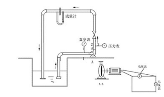
The water pump lift refers to the height at which the water pump can pump water. That is, the highest point that the pump can deliver water from the suction port of the pump. The head of the pump is usually represented by the symbol H, and its unit is meter. The head of the centrifugal pump is based on the centerline of the impeller and consists of two parts. The vertical height from the centerline of the pump impeller to the water surface of the water source, that is, the height at which the pump can suck water up, is called the suction lift, referred to as the suction lift; the vertical height from the centerline of the pump impeller to the water surface of the outlet pool, that is, the water pump can press the water up The height is called the pressure water head, referred to as the pressure stroke. That is, water pump head = water suction head + water pressure head. It should be pointed out that the head marked on the nameplate refers to the head that the water pump itself can produce, and it does not include the loss head caused by the frictional resistance of the pipeline water flow. When choosing a water pump, be careful not to ignore it. Otherwise, the water will not be pumped.
When selecting the type of pump, the merchant will generally ask the user how much the flow head is required. If the flow head cannot be determined, the correct type cannot be selected. Sometimes when asked about the flow head requirement of the customer, a few customers say that it doesn’t matter. This kind of statement is not allowed. There is no requirement for the flow rate, but there is no requirement for the head. The merchant must be informed of the actual working conditions such as the vertical height, the horizontal distance, how the pipeline is arranged, the number of elbows, the size of the pipeline, and the liquid to be transported, etc. in order to choose a suitable pump.
Calculation of water pump head
The head of the pump has nothing to do with the power, it is related to the diameter of the pump impeller and the number of stages of the impeller. A pump with the same power may have a head of hundreds of meters, but the flow may only be a few meters, or the head may be only a few meters, but the flow may be up to 100 meters. Baifang.
If the head of the water pump selected in the design is too large, the head will be exchanged for the increase of the flow rate, and the increase of the flow rate will increase the noise of the water pump. In particular, the increase in the flow rate also increases the load on the pump motor, increases the current, and increases the heat generation. It is still a trivial matter to "replace countless bearings", and it is very likely that the motor will be burned. Therefore, it is necessary to understand the calculation method of the pump head.
Method 1: Simple estimation method of pump head
Selection of HVAC water pumps: usually choose a centrifugal clean water pump with a specific speed ns of 130-150, and the flow rate of the water pump should be 1.1-1.2 times the rated flow rate of the chiller (1.1 for a single unit, 1.2 for two parallel units). According to estimates, the loss along the route of every 100 meters of pipe length can be roughly taken as 5mH2O, and the head of the pump (mH2O):
Hmax=△P1+△P2+0.05L (1+K)
△P1 is the water pressure drop of the chiller evaporator.
△P2 is the water pressure drop of the parallel connection in the ring, which accounts for the largest water pressure loss of the air-conditioning end devices.
L is the pipe length of the most unfavorable loop.
K is the ratio of the sum of local resistance equivalent lengths in the most unfavorable loop to the total length of the straight pipe. When the most unfavorable loop is long, the K value is 0.2-0.3, and when the most unfavorable loop is short, the K value is 0.4-0.6.
Method 2: Practical Estimation Method for Chilled Water Pump Head
What we are talking about here is the resistance composition of the closed air-conditioning cold water system, because this system is the most commonly used system.
1. Chiller resistance: provided by the unit manufacturer, generally 60~100kPa.
2. Pipeline resistance: including frictional resistance and local resistance. Among them, the frictional resistance per unit length, that is, the specific friction group, depends on the technical and economic comparison. If the value is large, the diameter of the pipe is small, and the initial investment is saved, but the energy consumption of the pump operation is large; if the value is small, the opposite is true. In the current design, the specific friction group of the cold water pipeline should be controlled within the range of 150~200Pa/m. When the pipe diameter is large, the value can be smaller.
3. Air conditioner terminal device resistance: The types of terminal devices include fan coil units, combined air conditioners, etc. Their resistance is provided by the manufacturer after calculating the coil configuration according to the parameters of the air entering and exiting the air conditioning coil, cooling capacity, and water temperature difference proposed in the design. Many rated working condition values can be found in the product catalog. This resistance is generally in the range of 20~50kPa.
4. The resistance of the regulating valve: Air-conditioned rooms are always required to control the room temperature, and setting an electric two-way regulating valve on the waterway of the air-conditioning terminal device is a means to achieve room temperature control. The specifications of the two-way valve are selected by the flow capacity and allowable pressure drop when the valve is fully open. If the allowable pressure drop is large, the control performance of the valve is good; if the value is small, the control performance is poor. The percentage of the pressure drop when the valve is fully open to the total pressure drop of the branch is called the valve authority. The water system design requires the valve authority S>0.3, so the allowable pressure drop of the two-way regulating valve is generally not less than 40kPa.
Based on the above, the pressure loss of the air-conditioning water system of a high-rise building about 100m high can be roughly estimated, that is, the lift required by the circulating water pump:
1. Chiller resistance: take 80 kPa (8m water column);
2. Pipeline resistance: Take the resistance of the decontamination device, water collector, water separator and pipeline in the refrigeration room as 50 kPa; take the length of the pipeline on the transmission and distribution side as 300m and the specific frictional resistance of 200 Pa/m, then The friction resistance is 300*200=60000 Pa=60 kPa; if the local resistance on the transmission and distribution side is 50% of the friction resistance, the local resistance is 60 kPa*0.5=30 kPa; the total resistance of the system pipeline is 50 kPa+ 60kPa+30kPa=140kPa(14m water column);
3. Resistance of the air conditioner terminal device: the resistance of the combined air conditioner is generally greater than that of the fan coil unit, so the resistance of the former is taken as 45 kPa (4.5 water column);
4. The resistance of the two-way regulating valve: take 40 kPa (0.4 water column).
5. Therefore, the sum of the resistance of each part of the water system is: 80 kPa+140 kPa+45 kPa+40 kPa=305 kPa (30.5m water column)
6. Pump head: take 10% safety factor, then head H=30.5m*1.1=33.55m.
According to the above estimation results, the pressure loss range of the air-conditioning water system of a similar scale building can be basically grasped. In particular, it should be prevented that the pressure loss of the system is too large due to uncalculated and too conservative estimates, and the water pump head is selected too large. lead to wasted energy.
Method 3: The head required by the cooling water pump
Hp=hf+hd+hm+hs+ho
hf, hd are the total along-path resistance and local resistance of the cooling water piping system, mH2O;
hm is the condenser resistance, mH2O;
hs is the lifting height of the water in the cooling tower (the height difference from the cooling tank to the nozzle), mH2O;
ho is the spray pressure of the cooling tower nozzle, mH2O, which is approximately equal to 5 mH2O.


